Introduction
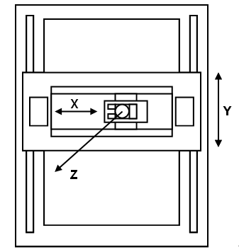
Figure 1. Box-in-box structure.
Synchronization motion control of multi-axis machine tools has become a significant issue due to the growing demand for high speed precise manufacturing. For such an application, two direct feed-drive linear servomotors are often adopted and arranged into a twin-parallel structure, the so-called “box-in-box” layout, to increase the thrust and stiffness of machine tools.The box-in-box structure adopts a pair of linear servomotors with mechanical coupling of one feed axis. Figure 1 shows an example in which the Y-axis is driven by the two linear motors coupled with the X-axis feed drive. An important requirement for high speed precision machining is the capability of the twin-parallel feed drives to follow the same command trajectories accurately for achieving a satisfactory positioning accuracy and also for reducing the synchronization error of the two parallel motors.
Strategies of the synchronous motion control technique can be classified into three categories: (1) synchronous master motion control, (2) master-slave motion control, and (3) relative dynamic stiffness motion control [1]. The framework of Category (1) is depicted in Figure 2, which is also called parallel synchronous control. As illustrated in Figure 2, the two servomotors receive the same motion command simultaneously and are controlled independently without considering the motion of the other. The advantage of this control scheme lies in its simple structure. However, accurate synchronous movement may not be guaranteed due to some possible effects such as unknown disturbances or unmatched model. This scheme is not suitable for the box-in-box machine tools since inherent disturbances always exist due to inevitable nonlinear dynamics, such as mechanical coupling. Note that asynchronous operation in motion control may result in diminished machining accuracy of the work-piece or even lead to breakage of the device.
To improve this shortcoming, Sarachik and Ragazzini proposed the master-slave control scheme of Category (2) and applied it to a biaxial system [2]. In comparison to the synchronous master motion control, the master-slave control operates in a cascade manner, enabling the slave servo system to follow the master with higher dynamic stiffness. Thus, the framework of master-slave control provides an alternative solution which allots a great deal of attention to synchronous motion control. As shown in Figure 3, a tandem control of two servo systems with velocity feedforward compensation was proposed by FANUC Ltd. to drive a single axis of motion [3]. Furthermore, another master-slave control based on speed/torque coupling was developed by SIEMENS [4].
The synchronous error can be eliminated in the master-slave framework if the disturbance occurs in the master. However, the servo lag between the master axis and the slave axis causes synchronization errors, while the unidirectional communication renders the master axis unable to detect the asynchronous movement when the slave axis encounters uncertain load disturbances. Therefore, the so-called relative dynamic stiffness motion control of Category (3) was proposed in which the synchronous error can be compensated by both axes. Figure 4 illustrates a position/velocity hybrid synchronous control proposed by Hsieh [5] with the concept of relative dynamic stiffness motion control. The same idea is also adopted by Yang [6] for controlling dual parallel linear servomotors. The key feature of relative dynamic stiffness motion control is that two motors compensate each axis in the velocity loop, but the position controller is only employed on the master. This framework can eliminate the servo lag error which occurs in the master-slave framework, while inharmonious movement in velocity loops can be compensated for in each axis. For further discussion of these three categories, one can refer to [1]. This paper utilizes relative dynamic stiffness motion control as the control strategy due to the benefits described above.

Figure 2. Parallel synchronous control.
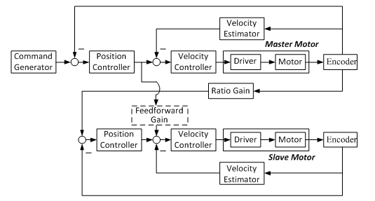
Figure 3. Tandem control with velocity feedforward compensation [7].

Figure 4. Relative dynamic stiffness motion control of [5].
Much previous research has focused on the velocity synchronization problem of two-axis motion. Recently, great progress has been made in utilizing the cross-coupling concept to solve position synchronization of multiple motion axes. Chiu and Tomizuka provided a necessary coupling effect, which was introduced to each axis by the proper choice of a Lyapunov-like function [7]. In addition to actual position and velocity information, the resulting control law requires prior knowledge of the desired trajectories and their time derivatives. Sun proposed a new control framework for position synchronization of multiple motion axes by incorporating cross-coupling technology into the adaptive control architecture [8]. The above-mentioned approaches are commonly applied to multi-axis motion control systems rather than configurations, such as the "box-in-box" system.
In the "box-in-box" servo mechanism, an accurate model of the controlled plant is useful for the design of the synchronous control, particularly in the presence of mechanical coupling. Therefore, this paper presents an identification method to identify the effect of mechanical coupling. Figure 5 shows a gantry-type machine tool which is driven directly by three linear servomotors in which a pair of motors forms the X-axis coupling with the Y-axis. An identification method is employed to characterize the dynamics of the mechanical coupling and a synchronous control scheme is also developed for the X-axis to achieve synchronized motion control of the coupled systems. For clarification and simplicity, the error of motion between these two parallel servo systems in the Y-axis is hereafter defined as the "synchronization error", which is the target to be eliminated by the proposed controller. It is noted that non-zero synchronization error causes the coupling to bend and generates force acting on both driving motors.
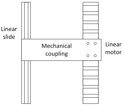
Figure 5. Gantry-type machine driven by a linear motor with a linear guide way.
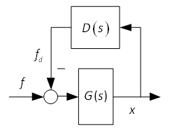
Figure 6. System model from the thrust command to the output.
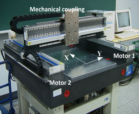
Figure 7. The linear motor driven machine tool.


 để chia sẻ bài viết lên facebook


 Trả lời kèm Trích dẫn